
So this is going to be a breif and poorly organized write up of what I did to get a tracer GT (2019) left control switch wired up and working on my 2016 XSR 900. At the same time I also replaced my headlight with an aftermarket one, added in a Smart Turn Signal unit, and added a relay for the headlight, so understand you may not need to follow all the same steps I did.
I went this route for a couple of reasons:
1. After 10k miles I was still hitting the horn button by accident
2. I want to add cruise control eventually in the future, and I wanted factory looking buttons rather than an add-on block of buttons.
3. My stock controls got full of dirt and even after disassembly and cleaning they simply didn't work very well anymore. Gritty and sticky instead of smooth so new switches were in order anyways.
Upfront I'll say that if I had to do it over again I might not use tracer GT switches. The Tracer GT has LED headlights and a 'headlight control' module which means that the headlight switch is designed for low amperage (to trigger a relay) rather than to feed a 60 Watt headlight directly. The switches off of a Super Tenere or some other bike with 'regular' headlights might be simpler, if you don't want the cruise buttons then the switches off of a regular Tracer (or basically any other bike) would work too. To work around the headlight switch issue I added a standard automotive relay.
Furthermore I'll state that after spending the first 15 years of my motorcycle ownership life working on a variety of older used bikes I absolutly despise anyone who modifies the main factory wire harness. With that in mind you'll notice that all my modifications were done on the 'switch' side of the wiring, so going back to stock for myself or anyone in the future should be as simple as unplugging my mod'd out switches and plugging in the correct 2016 XSR units from yamaha.
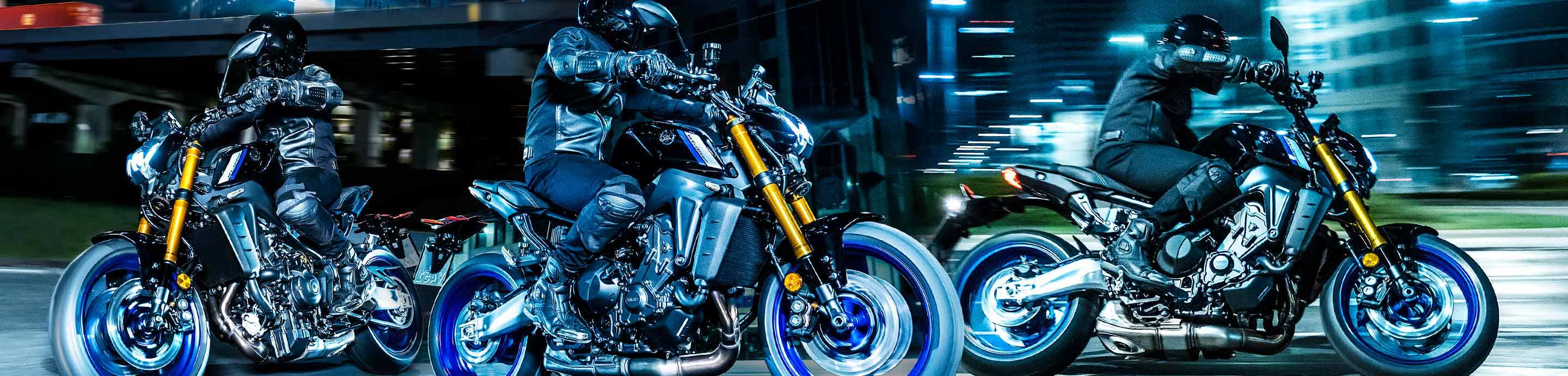
Preview of the finished product.
![Image]()
I went this route for a couple of reasons:
1. After 10k miles I was still hitting the horn button by accident
2. I want to add cruise control eventually in the future, and I wanted factory looking buttons rather than an add-on block of buttons.
3. My stock controls got full of dirt and even after disassembly and cleaning they simply didn't work very well anymore. Gritty and sticky instead of smooth so new switches were in order anyways.
Upfront I'll say that if I had to do it over again I might not use tracer GT switches. The Tracer GT has LED headlights and a 'headlight control' module which means that the headlight switch is designed for low amperage (to trigger a relay) rather than to feed a 60 Watt headlight directly. The switches off of a Super Tenere or some other bike with 'regular' headlights might be simpler, if you don't want the cruise buttons then the switches off of a regular Tracer (or basically any other bike) would work too. To work around the headlight switch issue I added a standard automotive relay.
Furthermore I'll state that after spending the first 15 years of my motorcycle ownership life working on a variety of older used bikes I absolutly despise anyone who modifies the main factory wire harness. With that in mind you'll notice that all my modifications were done on the 'switch' side of the wiring, so going back to stock for myself or anyone in the future should be as simple as unplugging my mod'd out switches and plugging in the correct 2016 XSR units from yamaha.
Preview of the finished product.